
Free Ebook: here is my free ebook describing how to construct this two wheeler. Includes problems, solutions, suggestions, photos, and code.
This latest 2.8 version includes Version #4 using a 395 gimbal motor and VNH5019 motor driver. It works well on fast turns too.
Spreadsheet to calculate gyroscope vehicle parms: (NOTE: you can only view this spreadsheet but the formulas are shown at the bottom so you can create your own.)

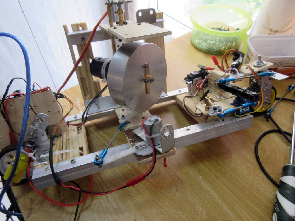
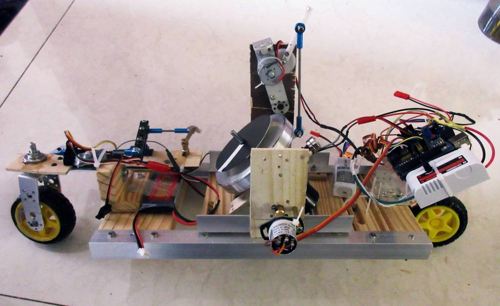
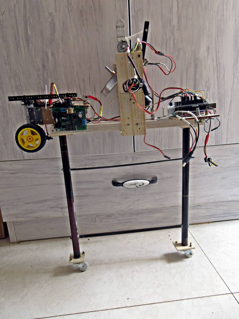
Here is my latest self balancing vehicle – it is an inline two wheeler using a mechanical gyroscope with active servo control of the gimbal. Took me a long time to get here but very satisfied that it works considering the haphazard construction techniques.
Weight of gyro rotor to Weight of vehicle is: .358g / 1.8 kg = 19.9% at 4000 rpm. It can be a little less than this before vehicle falls over. NOTE: now upgraded to 700 gram rotor, 100mm by 30mm.
Here is a link to an excellent document (pdf) to explain how to build a self balance a vehicle with a mechanical gyroscope by Mori, Hiroshi : https://thebbb.net/free/theories-and-experiments-for-gyro-monorails.pdf
_________________________________________________________________________________________
Update Jan 18,2021: I have posted videos of the latest version doing fast turns and balancing on a cable wire. I believe I have gone as far as I can with this project and that it has come to an end. It began about seven years ago with my first gyroscopic balancing two wheeler and evolved to this one using active gimbal control. I am happy with the results and am sorry too to leave it behind and move onto other things. I hope some others will gain some benefits from what I have learned and built and that they will move the technology, hardware and programming even further along.
I do not think there are real useful applications for this specific vehicle but what we learned along the way may have practical uses in other areas. Because a gyroscope operates so much more efficiently in a vacuum, perhaps one day they would be useful to stabilize a two wheeler on the moon – that would be fun.
Anyway, it has been a happy, sad, frustrating, enlightening, surprising journey and I hope it wasn’t entirely a waste of time. Thanks for reading and following along. God Speed.
Update Jan 14: Took gyro for a drive and wow, it turns left and right fast or slow. Had the video going but it was on my head and aimed too low and missed most of the action then one of the batteries died before I could get some good video so will have to wait for a few days for a new one. 395 motor and new algorithm definitely improved performance.
I built a cage around the gyro rotor, thinking the support would lower the vibration but in fact it seemed to increase the vibration and the gyro did not balance as well, so took it off. I guess if it was machined out of one piece of metal and perfectly straight, it might work but I don’t have the equipment. I have seen other gyroscopes that have a gyro rotor cage and they seem pretty smooth.
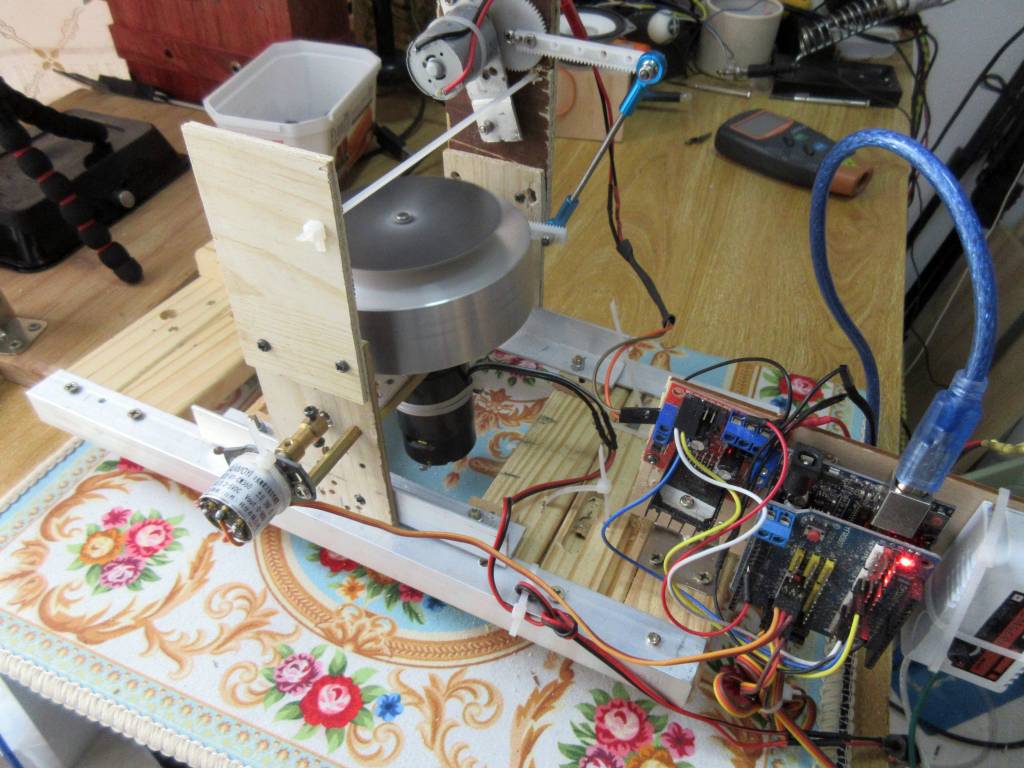
Update Jan 11, 2021: The gimbal potentiometer was loose and this caused terrible balancing. Tightened it up and it works pretty well now. Turns are better. Can still make it fall if I try but it works much better than last test run. I am putting a cage around the rotor so that the rotor is supported by two bearings, to see if it helps vibration. Then will make video. Then go back to 540 motor and try it again with the new algorithm which seems to capture disturbances much better. Wow, time is flying. Worked hard on this one for over a year but learned a lot. Now have the best hardware I think. I wished a real programming engineer could devise a good algorithm to control the gimbal as my math/physics background is so weak. Oh well, it drives better than any other self balancing gyroscopic vehicle with a single, horizontal axis gyro, that I have seen.
Update Jan 4, 2021: Disappointing results with the new potentiometer and ESP32 – it does balance but has too much erratic oscillations. I think it is due to the fact that the processor is faster but produces less length of time of power on cycle so the falling of the vehicle opposes the gimbal correction and it oscillates. My theory anyway. So, I am giving up on ESP32 and will go back to Arduino and try to tune my algorithm a bit more then make video. It does balance better now with the Arduino and 395 gimbal motor better than it ever has but still falls over on fast choppy turns. Perhaps will try to go back to 540 motor now that I have a better algorithm that makes corrections faster and use the belt and pulleys again.
Update Dec 25 2020: Merry Christmas one and all! I mounted a 395 sized dc motor for the gimbal control and it worked with no changes to the code though it could be tuned better because it has more torque than the 385. Will work on that for a while. Happy Holidays and hope the next year brings us better things than 2020 did. GB.
Update Dec 22: I have some more things I can try to improve balancing. Already, the changes in my algorithm have improved the disturbance capture a lot and the 385 motor works pretty good. (1) But I noticed I can look at my serial prints and tell what is happening with they gyro and I should be able to modify my algorithm even more. (2) I got a 395 motor which is just a bigger 385 motor and that should give me some more torque without being overpowering like the 540 motor was. (3) I found a 3.3 volt encoder for about 10 bucks that will work with the ESP32. I am finding that the faster I process, the more stable the gyroscope becomes. I took out all delay statements and process as fast as possible and that gives more stability. The ESP32 is 20 times faster than the Arduino Uno so if I can get that working, it should help a lot. So will be implementing these mods over the next month or so and hope to get a faster acting gyroscope.
Update Dec 18: This project is like a fusion reactor – completion is always 20 years away. Anyway, went back to Arduino and 385 gimbal motor and got it working pretty well so that it captures itself from major disturbances. Put on new potentiometer to measure steering angle and getting vehicle ready to test with batteries again to see if any improvement on sharp turns.
I am convinced that the faster the processor/processing time, the better it will balance as it has less time to fall during the time between measuring vehicle tilt angle and correcting angle error with the gimbal. I have lowered the delay time in the code and it has improved the performance though there is a little more jerky movement now because the motor correction is so abrupt.
I have ordered some AS5600 magnetic contactless potentiometers/encoders that I want to try get working with ESP32 to get the fastest response possible. Normal potentiometers are all 5 volt and will not work with the ESP32 which is 3.3 volt. The AS5600 works at 3.3 and 5 volts.
Update Dec 14: Found out that ESP32, which is 3.3 volt, cannot read potentiometer reliably – needs to be at 5 volt. So went back to Arduino Uno (5 volt) and pot reading is almost perfect. That is why the gyro was so erratic. Too bad as the faster processor would have definitely improved the gimbal control. But the mods I made to the code seems to have improved Arduino performance so will tinker with the code some more. Am using the 385 motor again so when the code is better will go back to the 540 which has considerably more torque.
Update Dec 10: Feeling so frustrated that I could not get the new computer to balance the vehicle that I almost gave up. But figured out that because it is so much faster, it caused the gimbal to pulse and therefore did not balance well. So put back in a delay and took out gradual motorPower increase code, so now it balances again but has some jerkyness that I have to smooth out. Went back to 385 motor for now so will work some more to optimize the code. If I get it to balance well I will go back and try 540 motor as I like the power but it strips gears too easily, the 385 does not have enough torque to do that. Perhaps brass gears will work. Also figured out a problem with my current algorithm that I need to address. Never ending project.
Update Dec 6: Going to go back to 385 motor as the 540 just doesn’t seem to work, strips gears. Tried it with pulley and belt and they have too much resistance. I even hooked up a servo directly to the gimbal and it sort of works but not well. Maybe the 540 would have worked if I had a good algorithm for using it but mine do not do the deed.
So, have to remount gears for 385. Hope it will work better with VNP5019 driver and a faster processor in the ESP32.
Update Dec 3: Woke up at 6am when I do my best thinking and realized why my algorithm does not work well. It oscillates badly because of the sector code I am using when it tries to return the gimbal to zero, it only applies power for a few milliseconds then shuts off and then because the vehicle is still out of balance it torques the gyro in the other direction and this turns the motor in the other direction. This process happens over and over and so results in oscillations.
What I need to do is: use an interrupt to constantly read gimbal position and not just read it when it has processed the motorSpeed code. I do not need the sector code, just apply power proportionally in the correct direction until I reach zero. I also need to track gimbal speed and if it is high then apply a brake before it gets to zero to prevent overshoot. That should more closely approximate how I control the gimbal when I use my RC transmitter to get the gimbal to balance. I figure if I can balance the vehicle manually with the RC gear, then it should be possible to balance it better with a computer. So, more coding needed.
Update Dec 2: Converted the geared gimbal controls to pulley and belt. Forgot that using a belt system would make the motor turn in the opposite direction than two gears so changed the code and it balances. Now just have to tune it as it balances pretty rough and I don’t know why. But have made all hardware changes I planned to do so will spend some time trying to better the code. Did notice that the pulley and belt tend to dampen some of the gyroscope vibration so that is a good thing but the gimbal does not turn as freely as it did with the gears but I don’t think in this gyro orientation that that matters as it does if it is vertical and depends on a top heavy rotor configuration.
DigitalWrite() function works as before with ESP32 but have to use ledcWrite() function in place of analogWrite(). Still using Arduino IDE but may install and try ESP32 IDE at some point as I don’t think I will go back to Arduino boards.
No hurry I guess as I have a new guitar and want to spend some time playing with that and doing some more writing.
Update Nov 17: Got ESP32 connected to my VNH5019 motor driver and it works. Also compiled my self balancing arduino code in ESP32 and it works and it really is 20 times faster in a loop() than the Arduino Uno – runs under 1 millisecond. Now just need to mount the boards on my vehicle, connect up the wires and see if it improves performance of gyroscope on the vehicle.
Update Nov 13: Found out the Arduino Due is very expensive for the board in China so will just bite the bullet and set up an ESP32 which is 20 times faster than an Arduino Uno. Should not require but a few code changes and a little more wiring. Want to find out if faster processor will increase vehicle stability. It should as I slowed down the Uno to simulate 5 times slower and the vehicle would not hardly balance, so I theorize that 20 times faster should really improve balance response time. Although, I still have to put delay()s in the code to allow the motor enough time to push the gimbal around. Taking out the delay() statements results in terrible gimbal oscillation and no balancing. Probably my algorithm is not the best but I have not had much luck in improving it lately.
Update Nov 1: I am convinced now that the 16mhz Arduino Uno processor is too slow to do a good job. It takes 10 to 20 milliseconds to go from sensor read to motor power and then some more milliseconds until the gyro motion takes effect. That is why the vertical orientation gyro works so much better because it is instantaneous due to the top-heavy gyro controlled by gravity. So, I am going to try an Arduino Due which is 5 times faster than the Uno and see if there is an improvement.
Have implemented gimbal speed with gimbal error routine and it seems to help some but not enough.
Update Oct 29: Kind of stalled now. Still does not balance as well as I think it can. Then thought about my algorithm. I need to use the velocity of gimbal combined with the gimbal position to generate the correct amount of motorPower. So will work on that for a while. No use trying the vehicle out as I know if will fall in fast turns until I can solve this issue.
Update Oct 23: Taking a step backwards and using a servo controlled counterweight to help with the balancing and during turns. With a single gyro, you need something to help in the turns, either turn the gyro gimbal or use a counterweight. I also found a mistake in the code that causes the motorPower to stay on too long if the gyro is far out of balance.
Update Oct 21: To turn sharply, the gyro must be turned in the direction of the turn OR a counterweight must shift in the direction of the turn. So, I put a servo with a counterweight on the vehicle and manipulated it during the balancing and it definitely smoothed out the balancing. So will incorporate the counterweight with my program to see if it will automatically smooth out the balancing, help with disturbances and help during sharp turns. Always something new to experiment with.
Update Oct 18: I am at an impasse. I went back to RC separately controlling drive wheel and steering. The vehicle still cannot make fast turns because the algorithm does not react quickly enough to correct the gimbal imbalance. Guess I will stop here for a while and work on other projects. I assume now that a serious self-balancing vehicle should have two gyroscopes, preferably in vertical axis orientation so that it instantly reacts to an imbalance. I do not want to go that route. I like the idea of a single gyroscope.
Update Oct 12: Had more pin conflicts and rewired my motor driver again. But still no joy. Going to have to try taking out one of my pin interrupt routines and do the vehicle drive motor with the RC gear and not the VHN5019 motor driver. This driver uses two PWM pins but then conflicts with Timer0, and Timer2 and causes crazy erratic behavior. Will take some time off from this project as it consumes too much of my time and is interfering with family business. This kind of project is definitely for experimenters and tinkerers who can solve their own problems. But it definitely shows that the gyro effect is fickle and hard to control – thus the failure of Lit Motors C-1 self-balancing motorcycle, the ThrustCycle and the Gyro-X car.
Update Oct 6: Gone on vacation for couple of weeks.
Have decided to use PID controller and it works pretty good, is simple to implement and it scales with changes in gyroscope RPM. Wired up 2200mah battery. Have implemented interrupt controls for RC TX and RX and they work well. Had to rewire motor controller PIN 2 to PIN 13 so that I could use 2 for the RC interrupt.
Ready to test vehicle with battery power.
Update Sep 5: All hardware is working now with 540 gimbal motor. But programming has stalled a bit. Going back to bang-bang algorithm as that seems to work best and is simplest. Just need to tune it but going on vacation for a few weeks so won’t get to work on it for a while.
Also I am able to use the RC controls and kick the vehicle up from resting on it’s side to a balanced position. That is pretty cool. Also using RC transmitter I can easily balance the vehicle so I know it is possible. Just need to get my algorithm to do what I do. The bang bang is working but it still wobbles a bit but can handle disturbances pretty well. Hope that tuning is all that is required.
Update Sep 1: Found out that pulseIn() function used to get RC RX channels for steering and throttle are very inefficient and add 60 millis to the loop and cause balance routine to almost fail so had to use interrupts on pins 2 and 3 and use my own functions to get loop time back down to 4 millis. Only tricky thing I had to do was cut a trace wire on the VNH5019 driver shield for pin 2 and solder wire to reroute to pin 13 so that I could use pin 2 to attach an interrupt to read pulses for throttle (channel 3 on RC receiver.) Was afraid it wouldn’t work but it works great. Hope this is all the surprises I will have now.
Still waiting for 2200mah battery to test vehicle.
Update Aug 31: The 540 gimbal motor is defintely powerful. I have implemented a routine to stand the vehicle upright from leaning on it’s side by quickly moving the gyro gimbal and then switch to self-balancing mode. Using channel 5 on my rc transmitter to kick the vehicle up and switch it off to switch over to self-balancing mode. I tried this with the 385 motor at full power and it did not generate enough torque to pick the vehicle up so a stronger gimbal motor would be required to balance the vehicle in the event of a powerful disturbance or a sharp turn. The 540 motor is powerful enough for those events.
Waiting on 16 gauge wire and a 2200mah battery for the vehicle as an 800mah battery does not provide enough current to balance the gyroscope well. (Also found that pulseIn() function was adding 60millis to main loop so of course it would not balance well.)
Update Aug 27: I was making this harder than necessary – I have changed to a Proportional (P of PID controller) bang-bang algorithm and it captures the rotor better on disturbances. Have implemented a PID routine to calculate motorPower, then turn motor on proportionally as long as it is not inside deadband.
Had to limit the 540 gimbal motor to 0 to 150 motorPower as it draws too many amps if the motor is stalled for more than a few seconds and the motor and wires get too hot (did melt some wires the first time I tried it so had to up the wire gauge.) The 150 is conservative and I have set it as high as 225 but will try to keep it lower to keep motor cool.
Update Aug 25: It looks like the 540 gimbal motor is a winner – it balances at neutral point pretty well but has plenty of torque to capture rotor if it is far from neutral point (target or setpoint). Just need to work on programming for it now to tune it up. 550 motor just had too much cogging and the amp draw was too high – 20 + amps if stalled. The 540 has about half that much draw and less cogging. So, 540 motor with VHN5019 driver seems to be a winning combination. Finally. Tested so many motors and drivers. Also, wiring is vastly simplified as the VHN5019 is a shield that plugs into the Arduino Uno and then I have a servo shield that plugs into the VHN5019. And, the VHN5019 can supply voltage to the Arduino Uno so only two batteries required to run the whole vehicle.
Update Aug 18: Got 550 working with VHN5019 driver – unfortunately the 550 is so massive that it cannot smoothly control the gimbal so it moves very jerkily – the rotor is just too large to change directions smoothly. It balances but not well so have two other options: 540 or 545 motor which is about half as massive or I can try two 370 motors side by side on the same gear – twice the torque. That is about all the options I can think of short of designing a new servo mechanism which I just can’t seem to figure out.
Update Aug 17: I tried out the 550 motor and melted the power wires because it draws so many amps (up to 85). So tried a geared JGA252430 motor that uses only two wires (plus two power wires) and has an internal motor driver. It is working but not sure how long it will last as it gets warm. So will test this motor for a while and if it doesn’t work, go back to trying the 550 (or a 540 that has half the amp draw) with heavier wiring.
There has just go to be a better design for a gimbal motor but I can’t imagine what it would be. Will have to work on that if these two motors fail to help.
Update Aug 15: Finally got VNH5019 motor controller working with 385 motor. It is an Arduino shield so plugs right into Arduino Uno – easy to configure. Have servo shield on top of it. Gets rid of a lot of wires. Since it can handle 12 amps per channel – next item is to replace 385 with 550 motor to get some real gimbal torque. So L298N handles 2 amp motors but loses voltage to heat. A4950 handles a little less than 2 amps but no heat so delivers a few more volts to motor but cannot drive 550 motor. VNH5019 handles 12 amps – shouldn’t have to go any higher than this. Took a lot of fiddling to get each of the motor drivers to work. I also tried a VNH2SP30 which handles 7 amps but guess I got a defective one because it would only drive one motor in one direction. So have tried 4 motor drivers and the VNH5019, though a few dollars more, is clearly the champ. Plus it can supply voltage to the Arduino Uno if you want.
I tried the 390 motor and it will not work as a gimbal motor because it cogs, way too much resistance.
Update Aug 12: The 370 gimbal motor will balance the vehicle within about 5 degrees from vertical, the 385 motor will balance within about 10 degrees and hopefully, the next size up motor (either 390 or 550) will balance within about 20 degrees where frame is almost touching the ground. Currently with the 385 and the A4950 controller, it can pick the vehicle up off the ground but not quite balance it again. Hopefully with the next motor/controller it will have the power to pick the vehicle up from the ground (about a 20 degree angle) and stabilize it.
I tried a new motor driver, the A4950 (2amp max) and it helps a lot but still cannot correct a gimbal that is very far from centered and the largest motor it will control is the 385 – perhaps a 390. I then tried the VNH2SP30 (7amp max) which would have run the 550 motor but it was defective. So have ordered a VNH5019 (12 amp max) ($7) motor driver and hopefully it will work to control a very off centered gimbal.
I also implemented some code to use milliseconds timer to get rid of awful delay() statement so that I can process some other things while waiting for the gimbal to finish moving. Very useful.
At some point I should implement the PID controller again to get a smoother balance. Right now it is basically just a P controller.
Tried the 390 motor but it won’t work because it cogs so badly – cannot easily turn it’s axle with your fingers – too much drag. So going to go with the 550 which I have already built the gear works for – just waiting on a bigger motor driver.
Update Aug 9: I replaced the L298N motor driver with an A4950 and wow, it almost doubles the torque. Haven’t got it tuned yet but it works so far. Looking forward to see if it controls the gimbal with more authority. I tested the torque on a 390 motor and the A4950 provides almost twice the torque as the L298N. Plus it only requires two wires per motor compared to the L298N which requires 3 for each motor. And it is cheap too. The only downside is that the driver cannot provide power for the Arduino so I will need a separate battery for the Arduino. Not a big deal.
The A4950 will not work with the 550 though (the 390 seems about the largest motor it will work with), so I have ordered yet another motor driver, the VNH3SP30 which will provide up to 7amps per channel. This is another 3 wire per motor driver but that is ok. Won’t try this one until I have worked out the A4950 to see how effective it is. Hopefully one of these drivers will allow the gyrocar to make faster turns.
Update Aug 2: I measured the ampere draw of various motors for the gimbal control using a 2 amp power supply. Note: the stall amp figures will not be accurate if using a greater than 2 amp power supply. I used a 7 amp power supply and for a 540 motor the stall amps went up to around 13 amps. I had to limit the power I used on the motor to keep the stall amps down. (went from 0-255 motorPower to 0-180).
Motor size stall amp (held shaft) no load amp draw 280 .20 .01 too small 370 .22 .01 barely works 380 1.87 1.0 won’t work 385 .7 ?? works well with VNH5019 390 1.33 .18 won’t work – cogs 395 ? ? work – using VNH5019 550 1.87 .86 wont work with L298NNow will order A4950 motor driver to see if the added voltage and amps will make gimbal motor more effective. Also will test 550 motor with it as I really want a more powerful gimbal motor. I am accumulating quite a collection of motors.
Update Jul 30: Decided to integrate radio controls directly into Arduino. The added benefit of doing this is that I do not need wheel encoders to see if the vehicle is moving forward or backward or if it is turning. Now will work on programming to see if I can turn the rotor during vehicle turns so it can turn faster. But if I stopped now I have basically succeeded in my goals.
Update Jul 29: Was “driving” my gyro vehicle and noticed interesting behavior – if I turn slowly during forward or backward motion, the gimbal motor is able to keep up and adjust the balance of the gyroscope to keep the vehicle balanced. But if I turn quickly, the gyroscope wants to stay in the same orientation but because the vehicle is turning, it applies a torque to the gyroscope and therefore might fall over; the gimbal motor cannot make an adjustment in time. So this is why the GyroX car turns the gyroscope when the vehicle turns – to keep the gyroscope oriented with the direction of the car. What this means is that I need two additional sensors – a potentiometer attached to the steering to sense when the vehicle is turning and a wheel encoder (or two) attached to one of the wheels to know if the vehicle is in forward or backward motion. This is what happens when you keep developing a self-balancing vehicle – it just keeps getting more and more complex to account for different forces acting on the gyroscope. This is probably why the Lit Motors Inc., C-1 self balancing motorcycle failed – they had over 30 sensors on their machine – a logistical and programming nightmare.
Update Jul 27: Installed new 385 gimbal motor. Has twice the torque of the 370 and works much better as it restores from disturbance better. Need to tune it some more. Will try using pulleys next to see if it smooths out linkage.
Update Jul 25: Decided to try LQR type of algorithm and it really, really smooths out the gyroscope. Still oscillates from side to side but does it less than with the IF-THEN conditional statements I was using. Like a PID but easier to implement.
P = (.08 * gimbalError) + (.5 * velP); // fraction of error and velocity of gimbal
powerTime = 30 * sq(P); // gradual curve up
delayValue = P * 10; // need formula as should curve down
Cool! Waiting on new more powerful gimbal motors as this 370 is maxed out when the rotor gets far away from setpoint.
Update Jul 22: Waiting on parts to convert geared gimbal to belt and pulley drive. Here is photo of new 5 mm axle (on the right) I had to install on gimbal to hold the large pulley. I epoxied the axle into the aluminum right angle piece. Love epoxy, use it for everything.
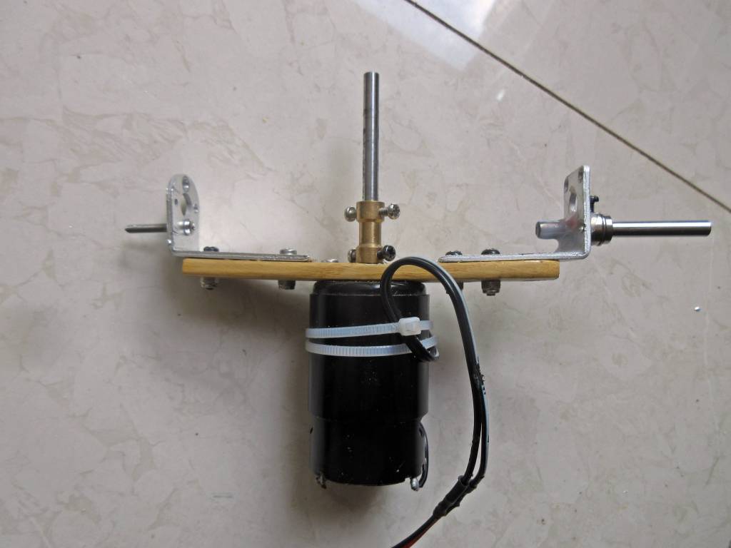
Gimbal motor is still under-powered but I figured out how to double the 370 motor power. That will be my next project after I finish installing the belt and pulley gimbal drive.
Update Jul 14: With the new orientation it does turn right and left now but still sometimes falls over: just realized a problem with Arduino microprocessor – if the gimbal motor is on for 50 milliseconds but the rotor has passed the zero or set-point – it has no way to turn off until the 50 millisecond cycle is finished and then it has to correct itself in the other direction. In other words, the gimbal will always be oscillating around the set-point because it has no way to shut off the motorPower cycle mid-cycle. So more programming required.
Second thing I realized: as the rotor gets farther away from the zero or setpoint, the motor needs more power to make a correction and since it is at full power it has to run longer (500 milliseconds). But this 370 motor just does not have the torque to make a quick correction so really need a bigger gimbal motor – the problem is that bigger motors have more cogging and this resistance or friction will cause the gyro to fall over. So two big problems to take care of: programming and search for bigger motor.
Next step: going to go with pulleys instead of gears to control gimbal. Much simpler and won’t run into torque changes caused by extreme angles on the gear/lever linkage. When gimbal is at its extreme angles, it loses balance quickly and the levers don’t have a lot of force. Found some 6:1 ratio pulleys that should work great.
Update Jul 11: Decided to play with it some more and go with #4 version (see picture below) with horizontal axis rotor as that is the only one that will allow left and right turns. I am getting it to stay balanced now and will play with program to increase speed of the algorithm. Gyro is same top-heavy (now side heavy) as last working with version #3 and vertical rotor axis. Just needs more dramatic correction if out of balance and definitely keep it away from extreme out of balance angles.
Update Jul 4: I have decided to stop working on self-balancing gyroscopes – six years is long enough, I have discovered the host of problems you must contend with, that the levels of complexity have no end and I feel that at my age of 66 years, I have more important things to spend my time on. It was fun, interesting, both satisfying and frustrating. I will continue to work on bettering the gimbal servo mechanism because that still interests me and I will document another chapter in my pdf book on the subject of gimbal orientation and then I will mostly escape this rabbit hole to perhaps find another one in some other field. I like to write and am currently working on AI subject short stories.
To anyone who pursues this topic – note that there are no easy solutions but I wish you good luck and good hunting and hope you will share your findings with me.
Update Jul 2: Wow, live and learn. There are two ways to mount the rotor in a gyroscope, with the rotor axis vertical or horizontal. There are pros and cons with both. Horizontal rotor axis: This allows a vehicle to make right and left turns without the rotor falling over. This is why the newly rebuilt GyroX car uses a horizontal axis even though the gyroscope was made by a boat gyrostabilizer company that normally uses a vertical axis rotor. The problem is that there is no natural precession to center the gyro in a zero degree balanced position. Also, this orientation requires more gimbal response time and power so your level of programming and mechanics goes up. Vertical rotor axis: This allows a vehicle to use natural precession to center the gyro in a zero degree balanced position, and less gimbal motor power required. Unfortunately, if the rotor is spinning clockwise, then the rotor will fall over in a right hand turn, though left turns are just fine.
Guess I will try using a horizontal rotor axis. I have already gotten this working but it loses it’s balance after a while and I am not sure why that is. I think I need to use a different program that does not rely on precession but rather just keeps adjusting the gimbal as close to the setpoint or zero position as possible. Update: I believe the rotor side must be heavier than the motor side as I discovered this when I built this side mounted gyroscope: https://www.instructables.com/id/Make-a-Self-Balancing-Gyroscope/ ) I am forgetting what I have already learned in the past. Will now modify version #4 to see if it balances better with a heavier rotor side (Note: heavier rotor side did not help.)
Update Jun 29: have mounted gyroscope on rotating bearing, hooked up a standard servo to rotate the bearing and tested it with my RC transmitter and it balances even if the bearing is rotated a few degrees in either direction. Will now set up the servo to synchronize with the steering servo and then remount the wheels to the vehicle frame and try it out to see if it helps on left forward turns. Will probably not help with rear right turns as it will turn the bearing in the wrong direction. That is why I think the GyroX car cannot make right rear turns because the gyroscope will fall over. Update: the bearing does not help at all.
Update Jun 27: Solved two previous problems. Just played with repositioning rotor on motor shaft until I got least amount of vibration. About the best I can do. Tried the dynamic balancing but it is dangerous and doesn’t work very well. #2 problem I wrote a subroutine to increase motor speed based on how fast the gimbal is turning. Work great and rotor is very stable at high rpm and always catches itself before it tumbles when disturbed. Will make a new video of that routine at work then install rotating gimbal.
Here is subroutine:
void doVelocityGimbal() {
////////////////////////////////////////////////////////////////////////////////////////////////////////////
// every so many milliseconds, check rotation velocity of gimbal, if fast then increase P, if slow then decrease P
////////////////////////////////////////////////////////////////////////////////////////////////////////////
if(velCurrentMillis – velPreviousMillis > 300) {
velElapsedTime = velCurrentMillis – velPreviousMillis;
velSpeed = (abs(gimbalAngle – velPrevGimbalAngle));
velSpeed = velSpeed / velElapsedTime;
if (velSpeed > .005) {velP = .2;} // fast so increase P to stop gimbal torque faster
else {velP = 0;} // slow so decreaase P to let gimbal stay in this area
Serial.print(“velElapsedTime= “);Serial.println(velElapsedTime);
Serial.print(“gimbalAngle= “);Serial.println(gimbalAngle);
Serial.print(“velPrevGimbalAngle= “);Serial.println(velPrevGimbalAngle);
Serial.print(“velSpeed = “);Serial.println(velSpeed);
Serial.print(“velP= “);Serial.println(velP);
velPreviousMillis = velCurrentMillis;
velPrevGimbalAngle = gimbalAngle;
}
}
Update Jun 18: got two problems I have to deal with now: #1. vibration of the rotor coming I think from the poor fit of the shaft adapter to the motor shaft – sometimes it is smooth and sometimes terrible vibration. Will have to try a dynamic balancing contraption that I will build using some small bearings and a couple of bottle tops. #2: the gyroscope goes out of balance after a while. I need to optimize the code but will fix the vibration problem first as it is so loud it vibrates the table and probably the neighbors ceiling. So this is going to take a while. No hurry I guess. Have to get both problems addressed before moving on to the rotating gimbal.
Update June 16: Above is video of new rotor. This will be version #3 of my self-balancing vehicle using a new 720 gram aluminum rotor. Much smoother operation. Need to modify program parameters to control it as the gimbal motor is just barely balancing it with the parameters used for a rotor half of this ones mass. Was able to use most of previous motor/gimbal mount.
Update June 14: Got my new rotor which is twice the thickness of the old rotor. Shaft hole is a tiny bit larger as the machinist could not promise 5.01 mm so it is probably 5.04 but better than the old 5.1 which was a really loose and sloppy fit. Very heavy, 700 grams. Balance point is at lower edge of rotor so have to build new gimbal mount. Going to take a while. Hope it will not wear out motor bearings too quickly. This rotor will produce a lot of torque and hopefully enough to allow me to use the gimbal rotating bearing to counteract left turn fall overs.
Got new rotor mounted and it balances pretty nicely. Next, test gimbal motor with it and modify code to account for more torque needed to control gimbal.
Update June 8: Haven’t done anything on this project until today: found a CNC machinest to make me a new rotor, 1000mm by 30mm, twice as heavy as my first one. With this one I should be able to put back in my rotating gimbal and test left turns. Cost 130rmb (about $20).
Update April 21: I have balanced the stripped down vehicle #2 (no steering or power wheels or batteries and weighs 1.5kg) at 1850 rpm. This is the minimum it will balance at so ratio of rotor to vehicle weight is: 24% which is what my fully equiped vehicle with a new 720gram rotor would be. I think it needs to be at that ratio to balance well like Schilkovski’s gyrocar. Also at version 2.1 of my book.
Update April 15: I stripped the vehicle down to just the gyroscope and gimbal controller and did an experiment where I started out at high CG of 13 cm from ground and then lowered by about 1 cm at a time down to 2 cm from ground. Definitely the gyro gets more stable the lower you go, especially when recovering from disturbances. It won’t balance at all at 13 or 14 cm. 2800 rpm throughout the experiment. See following video:
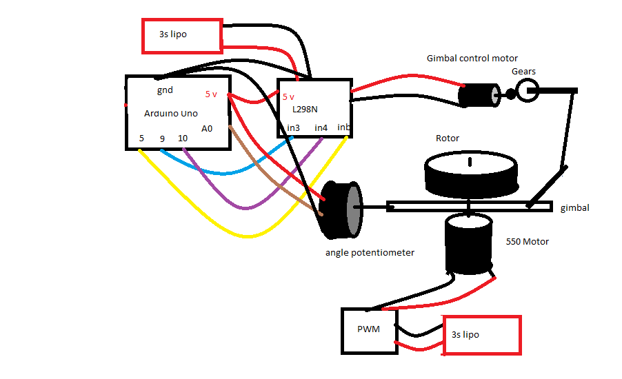
Component and wiring schematic:
Update April 14: I stripped the steering and rear wheel off to get weight down to 1.5 kgs. Then I am using two chop sticks as the “wheels” to see the effect of different heights of CG from the ground. Started at 10cm off the ground and it would not balance at 2800rpm. Dropped to 9cm and it balances. The lower I go the better balance. Went down to 2cm and is treats disturbances better the lower it goes. So now need a new rotor before I can really do anything else.
At 1.5kgs it balances quite well and takes disturbances better. At 2.5kgs (with steering and power gear) disturbances cause it to become unstable. Really need a heavier rotor but cannot find a machinest here in china for the job. The only other alternative is to programmatically fix it.
Found C-1 patent that shows how to calculate how much torque required to return 30 degree angle to vertical. Will have to do that someday. https://patents.justia.com/patent/9273961#description
Update April 7: Was driving the gyrocar today and noticed, it falls on sharp left turns (gyroscope spins to the left) but ALSO falls making turns in reverse to the right. It is fine on forward right turns and backward left turns. Interesting but not surprising.
Also I think I am at the limit of balance and really need a larger rotor for more vehicle balance control. I can also try increasing program parameters for operation at high rpm to correct imbalance. Am trying to find a machinest for a new rotor with twice the mass (360 to 720 grams) but don’t know when that will happen so am trying to improve operation programmatically.
The nice thing is that I can now balance at 3000 rpm with the electronic gimbal controls but with the controls turned off, it will not balance at all. So I do have some control. Wish I could figure out a better algorithm than the sector programming I am currently using as it seems limiting.
Update April 4: I measured the minimum rpm to balance the vehicle and using gyroscopes.org/math online calculator, I determined the following:
360 gram rotor @ 2000 rpm = 580 grams of torque = 580g/2000g (wt of vehicle) = 29% (fails to balance)
360 gram rotor @ 2700rpm = 785 grams of torque = 785/2000g = 39% (balances)
So, it takes about at 40% ratio to balance this vehicle
Update Mar 28: The biggest problem with single rotor gyroscopic vehicles – turning. I wondered why the vehicle turns so nice and sharp to the right but will fall over if I turn very quickly to the left and I think I have figured it out. If you turn in the same direction as the precession ( which in this case is to the left since the gyroscope is spinning to the left or counter-clockwise) and you turn faster than the precession rate then the gyroscope will fall over. So, how to prevent that?
- You can prevent it by turning the entire gyroscope to the left at the same speed as you make the turn and then there will be no loss of precession. But this is a lot of work as it means you need another gimbal on the gyroscope and a control mechanism to turn the gimbal when steering to the left. I was going to do this one and had built a bearing into the gyroscope frame but the bearing weighed so much that my vehicle would not balance well. Will come back to this when I get a larger rotor.
- Another way to cope with it is to speed up the rpm of the gyroscope rotor. But that requires hooking your gyroscope rotor up to the microprocessor – a lot of work and it probably still wont work as you cannot increase the rpm very quickly.
- I’m not sure this way will help but you might tilt the rotor forward during a left turn to roll the vehicle to compensate for the turn. I will try this method first.
Update Mar 25: rebuilt gyro vehicle on new chassis but didn’t balance very well – oscillating terribly. So took off 400 gram circular bearing and still does not balance well. Two potential problems: 1. Using soft wheels that are slightly flat creates a side force. But don’t think that is it. 2. Lowering the axis of the gimbal too low robs the gyro of power for side to side torque. Like an inverted pendulum, it needs to be higher to exert less force to balance but not too high. Too low takes more torque to correct imbalance. Too low = less force required but higher speed. Too high = more force but less speed to correct. So need a balance between the two. Guess I have to raise the gyro until I can get a heavier gyro rotor. NOTE: took care of this by changing program parms.
On the note of the gyro material: steel is 2.5 times as dense as aluminum, and brass is 2 to 3 times as dense as aluminum. Aluminum is poor choice for rotor unless you don’t care how big the dimensions are.
Update Mar 20: Built new chassis and added gyro to it – worked but very rough balance. Then discovered that by lowering powerTime variable then it smooths out corrections fantastically. Went from value of 50 to 5. Now nice and smooth corrections. This makes sense as I lowered the CG of the gyro and therefore it requires less corrective force. At 50 I was over-correcting.
Calculated that 16% rotor to total weight is minimum I can balance with.
Todo: 1. add servo to move gimbal bearing.
2. add steering gear.
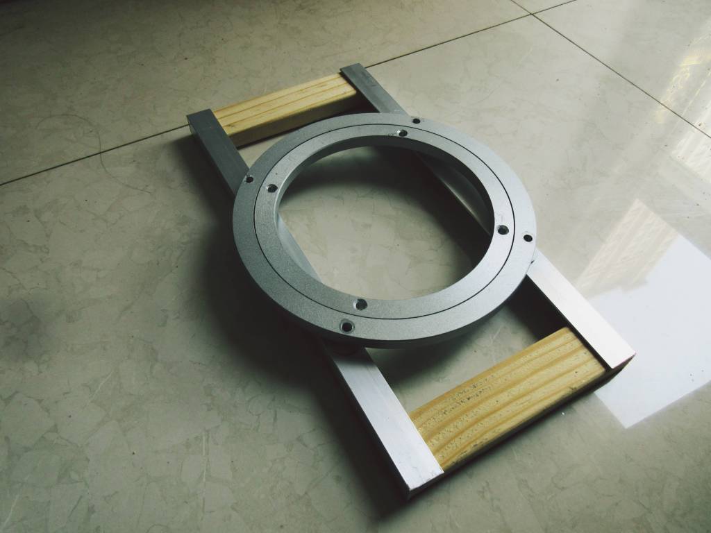
Update Mar 18: New frame with circular bearing so that I can turn the gyroscope when the vehicle turns.
Update Feb 28: put batteries and steering gear on new chassis, and had to retune parameters to get it balancing again. Then made following vide. Left and right turns. Now need to wait on getting final parts to build final version where I will turn the gyroscope with the steering to make turns better.
Update Feb 27: rebuilt the chassis to lower the center of mass closer to ground. It runs very smoothly even at low 3300 rpm. The lower the COM and lighter you can make the gyro vehicle has a huge effect on its performance.
Update Feb 26: build stilts to raise gyro platform from 10cm to floor, to 40cm to floor. Will not balance now even at 10,000 rpm. Makes sense as it acts like a long lever when falling over and this gives greater torque to gyroscope. Therefore it would require much larger rotor and/or higher rpm to counteract falling induced torque. So, the lower the CG of the gyro, the better. I plan to rebuild the chassis to lower the motor where it almost touches the ground – control should be even easier.
Update Feb 22: added a potentiometer to the steering servo to know when I turn so as to move balance point during turns to keep rotor balanced. First I added a wire to the steering servo potentiometer wiper and ran it and a ground to the Arduino but for some unknown reason it occassionally caused the servo to do erratic behavior so had to resort to an external pot that I stole from a standard servo and it works great. Now when it detects a turn I move the balance point forward or backward by 50 to keep the rotor balanced. Not perfect but much better than without it.
Next, take video of using the steering servo pot. Then a video of driving it with sharp left and right turns. Then try 540 sized motor to reduce voltage requirements. Will at some point need a 2000mah lipo as the 800mah runs dry in 5 minutes.


Update Feb 21: Added machine learning code to program to randomly choose some variable values in the program and measure the error over 100 cycles and keep the variable values that result in the least amount of error (balance point – actual gimbal angle). Works good.
Also added a wire to the steering servo to feed the angle of the servo to the Arduino and if a left or right turn then moves the balance point a corresponding amount to restore balance. Need to work some more on this as it rotor falls when quickly going back to neutral point.
Update Feb 17: Part 3.1 video: driving around. Good right turns, left turn is limited by mechanism that needs some work. Exponential moving average smoothing has really made the gyro stable. Replaced powered wheel AA batteries with 3s lipo battery and adjustable LM317 power supply. Now have lots of power. Also using two 3s lipos for Arduino Uno and to power gyroscope motor.
Update Feb 15: Plotting angle reading of gyro gimbal on serial plotter and it shows little spikes that I think may be due to sloppy gear linkage. Also used Exponential Moving Average smoothing routine that works well to get rid of spikes. Will make a new gear/motor mount at some point to see if spikes go away. Gyro balances nicely even at low 4000 rpm (6volts).
Plot should be sine wave but it goes up, comes back to center then down then back up. Not sure what is happening there but pretty erratic.
Got steering working by adding a standard servo. Will post video when I get vpn back.
Here is screen print of smoothing plot:

Update Feb 14,2020: Now balancing pretty well at 8000 to 10000 rpm. Even balances at 4000 rpm but wobbles quite a bit. Replaced wheels and front wheel is motorized and took video of going forward and backward. Unfortunately the AA batteries got depleted very quickly. So have ordered a rechargable lipo battery. Have added a standard servo to be used for steering.
Want to try a CG self-correcting routine to find optimum CG. Algorithm: for CG from 350 to 400; measure error for 1000 cycles; divide total result by 1000; keep lowest error.
Part 2 video: added powered wheel and rear wheel.
Video of first successful balancing (Part 1):
Specs:
- Arduino Uno
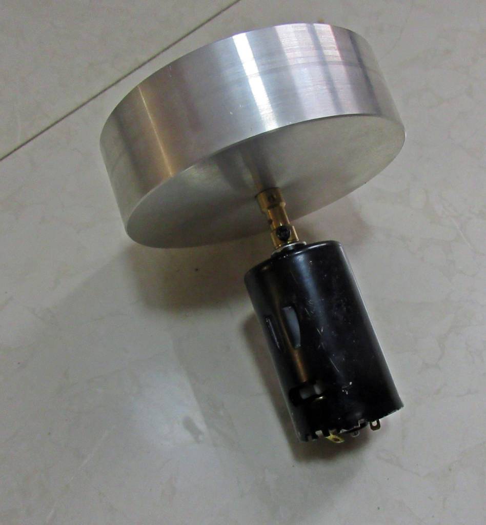
- machined aluminum rotor , 360 grams, 10cm by 1.5cm (updated to 720 grams, 10 cm by 3 cm)
- 550 12volt 18000(no load) dc motor
- 370 motor for gimbal control (updated to 540 motor) (now updated to 395 motor)
- P3022 non-contact potentiometer (required for no friction and precision values)
- yellow geared 110 rpm motor for mobility
- L298N motor driver (must have heatsink) (updated to VNH5019 12 amp controller)


Jim’s Free Ebooks
Here are free pdf downloads of various books I have written.
In these stories we look at human nature as it intersects with AI, AI being loosely termed to cover androids, cyborgs, thinking machines, brain implants, and robots – all IMAGO HOMINIS – made in the image of man. The world the stories take place in is slightly in the future, assuming we will have self-conscious and self-aware machines sooner, rather than later. And there are a few aliens as well.
(Click on image to download pdf file.)
A how and why-to instruction guide to art drawing and painting. Version 2.1.0 Contains lessons learned from years of artistic endeavor in portraits, still-lifes and landscapes. Acrylic, oil and pen and ink. Illustrated with 45+ drawings and paintings. No nudes. Updated from 11 years ago with new paintings.
(Click on image to download pdf file.)
Speculation of the details of Bible stories is what creates our mental pictures of how they took place. This book is a compilation of fifty, one-page summaries and opinions of each chapter of Genesis. I started writing this book as a blog – it was a personal challenge to see if I could come up with some thoughts about each chapter. But soon it became more of commentary with a personal life application.
(Click on image to download pdf file.)
A compilation of forty one-page summaries and opinions of each chapter of Exodus. This is a continuation of the commentary above on Genesis.
(Click on image to download pdf file.)
This booklet (version 2.7) outlines the principles and the methodology for building a self-balancing two-inlined-wheeled vehicle or model using a mechanical gyroscope. It includes photos and descriptions of how I build my working model as well problems encountered and solutions, suggestions and my actual Arduino code.
(Click on image to download pdf file.)